In Revit 2018 How Do I Make a Door Cut Into a Wall in Creating a Family
In the previous blog post , we've covered all the bones principles to properly create a door family. In this tutorial, we volition apply this knowledge to create a elementary swing door. The door will accept a steel frame and will exist adapted more often than not for an interior use on drywall. Information technology volition take a uncomplicated console with no glazing.
It will include a elementary handle lever hardware on both side of the panel, with a customizable strike distance height. The door swing will be customizable with an bending parameter. It will include a formula to calculate a value for Crude Height and Crude Width dimensions. The materials will be customizable inside a project for the door frame, door panel and all the hardware.
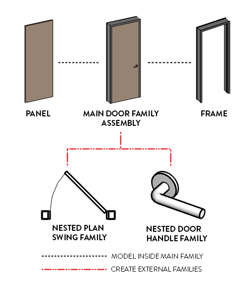
Some elements will be included directly inside the family, but some other elements will be inserted as nested families.
1- CREATE NEW FAMILY WITH THE DEFAULT TEMPLATE
Create a new family. Use the Metric - Door or Imperial - Door default Autodesk template.

This door family template is made for a residential wooden door family unit by default. Since we are building a door with a steel frame, you'll demand to delete a few elements. Go to the plan view. Delete the trim elements.

2- CREATE ROUGH DIMENSIONS REFERENCE PLANES
Let's create boosted reference planes to adapt for the full door opening that includes the frame. Go to the front end height view. Create new reference planes like displayed in red in the paradigm below. Don't worry about dimensions for now.

The red reference planes are used for more than clarity in the tutorial, simply it'southward ok if y'all use the standard green ones.
iii- CREATE FRAME THICKNESS PARAMETER
To fully automate the complete door opening, you need to create a new Frame Thickness parameter. Become to the Family Type menu. Click on the small icon to create a new parameter. Use the settings as in the image beneath.

4- CREATE ROUGH WIDTH AND Height FORMULAS
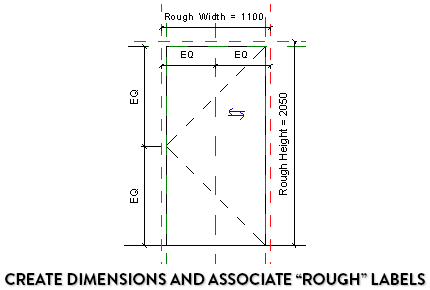
Blazon in a standard value for the Frame Thickness, like 50mm. At present, type in formulas similar in the image beneath for both the Rough Width and the Crude Acme parameter. These values are calculated past adding the frame thickness to the door height and width. Subtract a number to account for the overlap betwixt the frame and the wall. In this instance, we utilise 19mm.

five- ASSIGN ROUGH DIMENSIONS TO REF. PLANES
Now, become back to the family superlative. Add a new dimension between the two red vertical reference planes and the central one. Click on the EQ button.

Create new dimensions equally illustrated beneath. Assign the "Rough Width" and "Crude Height" labels.
Maybe you should download our new pamphlet about doors. Information technology contains this blog post in PDF format and many more useful tips.

half-dozen- LOCK OPENING Cut TO ROUGH WIDTH /HEIGHT
In the elevation, select the Opening Cut. Click on Edit Sketch. Apply the Marshal tool (shortcut: AL) to align each boundary line to the red reference planes. Click on the Lock icon to lock the constraint. The opening cut volition at present include part of the frame instead of just the door console.

7- MODEL DOOR PANEL IN ELEVATION
Stay in the elevation view and select the Extrusion tool. Use the Choice Line tool and click on the greenish reference lines assigned to the Superlative and Width. Lock all the purlieus lines. And then, utilize the Trim tool (shortcut: TR) to cut the excess line segments. Click on the greenish cheque to complete.


8- ASSIGN DOOR THICKNESS IN PLAN VIEW
Go dorsum to the plan view. Create a new reference aeroplane beneath the exterior wall face, equally in the image below. Create a dimension between the reference planes and assign the "Thickness" parameter to it. Brand sure to lock the thickness parameter. Use the Marshal tool (shortcut: AL) to match the panel to that new reference plane. Click on the lock icon.

nine- Deactivate Panel VISIBILITY IN PLAN VIEW
The 3D door console we've just created should exist visible in 3D views and elevations, just non in a plan view. Instead, we're going to load a programme swing family subsequently.
Select the door panel. In the example parameter, click on Visibility / Graphics Overrides.

Hey mate! Do you similar this mail service? Check out our popular BASICS package. It is designed to assistance yous acquire Revit in a spirit of fun and simplicity. Information technology has been downloaded past thousands of users. Click on the prototype to learn more.

10- CREATE A SWEEP FOR THE DOOR FRAME
Go to the pinnacle view. Select the Sweep tool. Click on Pick Path, then select the 3 edges of the opening cut. Click the green bank check to complete

eleven- DRAW THE FRAME Contour IN Plan VIEW
Draw the sweep profile in the flooring plan view. Draw the boundary lines every bit in the paradigm below. Make certain to lock all the dimensions. Create a new vertical reference airplane with the "Frame Thickness" parameter assigned. Keep a 5mm altitude from the door console to the frame heart section. If you want, you tin can include the frame thickness (like on the right image). Examination the frame by changing the door width and the default wall thickness.

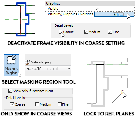
12- CREATE A COARSE FRAME MASKING REGION
When working in view using the Coarse setting, you might desire to come across a simple frame instead of the complex sweep we've created. Select the frame sweep and click on Visibility/Graphics Settings in the instance backdrop. Uncheck visibility for fibroid setting. And so, use the Masking Region tool with Frame/Mullion [cutting] lines and create a rectangle that is locked to the reference planes. Make it visible simply in coarse views.
thirteen- ASSOCIATE A NESTED PLAN SWING Family unit
Earlier, we deactivated the door panel visibility in plan view. Now, it'southward time to load a nested Plan Swing Family. You lot can apply an Autodesk made family, but it would exist smart to create your ain program swing family unit. Be warned: making such a family is not an easy task. We describe all the steps on the Revit Pure Pamphlet you can download at the bottom of this mail service.
When the family is ready, make certain to acquaintance the Thickness, Width and Swing Angle parameters to the main door family unit. Marshal and lock the swing family to the reference planes in the master family.


xiv- LOAD HARDWARE FAMILIES
Now, we'll insert an Autodesk Handle Lever Family. Go to the Insert tab and click on Load Family. Become to the Hardware subfolder in the doors category. Identify the family unit in a plan view. Align and lock to reference planes. Set and lock distance from the door panel border.


Get to the meridian view. Create a new horizontal reference airplane. Create a dimension from the base level. Assign a new parameter called Strike Distance. Run across tip 4 if y'all don't call up how to create a new length parameter. Align the center of the handles to this reference plane and lock.

Become dorsum to program view and disable the plan view visibility for the handles.

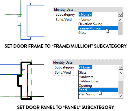
15- ASSIGN SUBCATEGORY TO ELEMENTS
To properly control the visibility and graphics of each door component, yous demand to properly assign the correct subcategories. Go to the program view. Select the door frame sweep. In the instance properties, set information technology to Frame/Mullion. Repeat the same steps to place the door panel in the Panel subcategory. Brand sure to identify any door element to the right subcategory.
16- CREATE Material PARAMETERS
Yous demand to create new textile parameters for the door frame, panel and all the hardware components.
Click on the door panel. In the instance properties, click on the minor rectangle. Create a new parameter chosen Panel Material. You'll exist able to assign a material in one case inside a project. Repeat the same step for the frame and create a Frame Fabric.

Do you desire to become this blog post in PDF format? With fifty-fifty more than bonus content? Check out our latest pamphlet publication about door families. You will even learn how to create a door swing family unit.

Source: https://revitpure.com/blog/16-steps-to-create-a-door-family-in-revit
0 Response to "In Revit 2018 How Do I Make a Door Cut Into a Wall in Creating a Family"
Postar um comentário